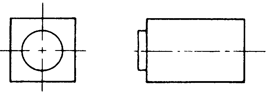
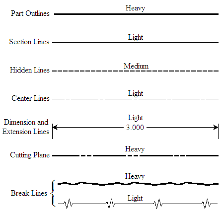
Line weights are a big part in clarity of and the conveying of information. Center Line Center lines are used to represent axes of symmetry.

Chase Block
The line weight is.

. It is used for ghost outlines and bend. The pointed edges are in the form of an arrow. Composite poses for example are a convention of Paleolithic art.
Your CAD drawing do show that it is possible to ascertain knowledge and experience when done well. That means the ways an eras objects typically represent figures spaces lines etc. Hidden Line Hidden lines are used to represent edges and boundaries that are not visible from the viewing direction.
Figure 14 Example of a Combined Drawing PID Electrical Single Line and Electronic. The purpose of a sectional view is to allow for a more detailed and close up view of a specific area of a part. Equipment codes are defined in the Equipment Naming Conventions 3.
Standards and Conventions. For general engineering drawings the types of lines recommended by the Bureau of Indian Standards shown in table 2 must be used. These are the most used type of drawings in the piping industry and take a good deal of practice to fully understand how to draw.
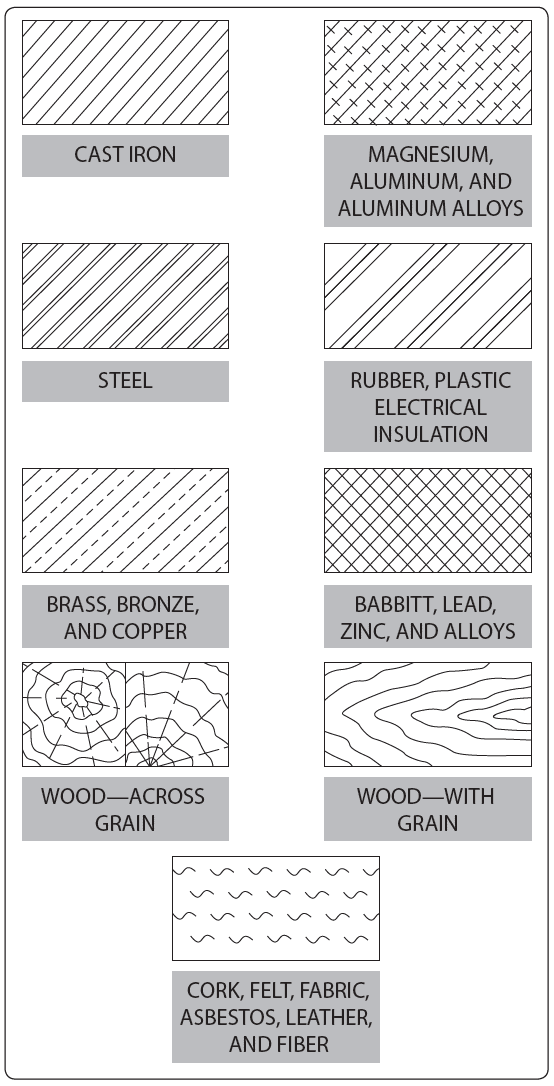
Lines are used to show dimensions and hidden surfaces and to indicate centers. Visible Line Visible lines are used to represent visible edges and boundaries. Examples in this gallery include the symbols for cast iron wood brass copper glass and more.
The Mechanical Drawing Conventions ClipArt gallery offers 48 illustrations of the conventions used to represent different materials in mechanical drawing. Drawings are composed of different line conventions because there are many different types of objects and each line convention is useful for accuratelyefficiently conveying information for a specific or broad range of shapesfeatures. What is the purpose of a sectional view.
The person who will read drawings have to learn what they mean. Obviously if the same kind of line is used to show these variations a drawing becomes a meaningless collection of lines. B Line styles Contrasting line widths and types are used within a drawing to delineate types of information.
Arrowhead Lines are used. The line weight is thin 03mm0012. Every drawing is composed of lines.
For wider objects a long break might have more than one pair of zigzag lines. Looking at the drawing. At the end of dimensional lines.
Engineering Symbology Prints Drawings Electronic Diagrams Schematics 3 Electronic Schematic Drawing Symbology Of all the different types of electronic drawings. Line width line typestyle and color of the layerlevel they are on. Why are drawings composed of different line conventions.
Conventions are the ways something is usually done. Why are drawings composed of different line conventions. The weights are like the tone of your voice when talking or singing.
Technical drawing Lines are used for different purposes to provide specific information for designers manufacturers etc. Lines mark the boundaries edges and intersection of surfaces. This line is similar to the Dash Thin Lines with Dots except that it has double dots within it.
In the image seen here the bisons profile view is a Paleolithic convention. For documents of general interest for example management and quality assurance the pseudo-equipment code PM shall be used. Why are drawings composed of different line conventions.
This ensures that every drawing produced within Ireland and the UK relating to a building project will follow the same standard principles. 513 DOCUMENT TYPE CODE The Document type code is composed of 2 characters. The line weight is thick 06mm0024.
There is no one line that is used today that has the function of all of the. They best represent what is being built and what it will. The list of document types and corresponding codes is shown in table 2.
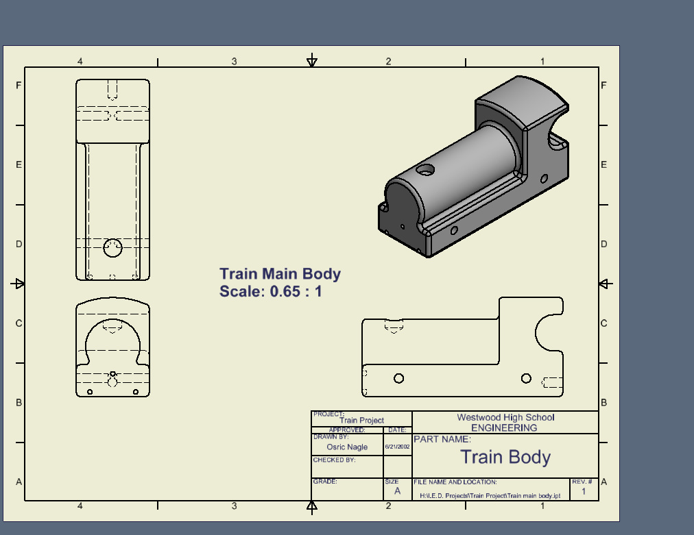
Technical Drawing Line Types. In the construction industry all drawings are carried out to a British Standard referred to as BS 1192. Drawings are composed of different line conventions in order to allow certain areas to be seen such as holes and how deep they go in.
British Standards 308 7308. Line types are also a language type to communicate between technical people. They are used to show the cast or the rough shape of a part before machining.
For drawings made to a large scale special conventions are used that apply to drawing breaks in such things as metal rods tubes or bars. It is a meaningless sequential number supplied by the EDMS. The thickness of the lines must be chosen according to the type and size of the drawing from any of the six groups given in Table 1.
In art we refer to conventions of style. Drawing sectioning are essential means of communicating ideas. Engineering Drawing Dimensioning for Coursework projects in Design technology.
Chapter will review the basic symbols and conventions used in both types of drawings. The line starts and ends with the long dash of 15 mm with about 15 mm space between the long and short dashes. They are lines with pointed edges at one or both ends.
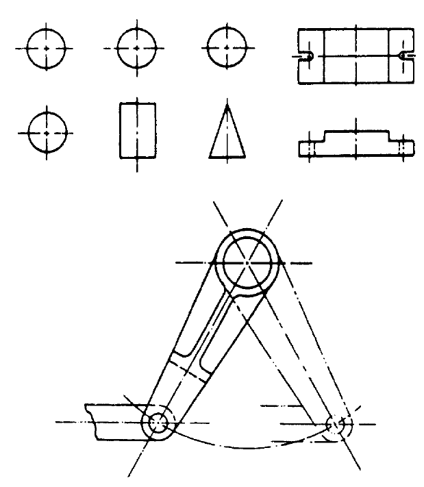
They are used to represent alternate positions of moving parts adjacent positions of related parts and repeated details. Different Types of Electrical Diagrams and Drawing. Drawings are composed of different line conventions because not all the lines are going.
An isometric drawing has both visible surfaces drawn at 30. In Electrical and Electronics Engineering we use different types of drawings or diagrams to represent a certain electrical system or circuitThese electrical circuits are represented by lines to represent wires and symbols or icons to represent electrical and electronic componentsIt helps in better understanding the. Document Type Identifier 514 NUMBER The number field in a document name is composed of 6 digits and may be used in three different ways.
Many far to often most CAD drawings are flat boring monotones. 1 Width The five line widths defined below along with options 1 through 3 are considered sufficient and should not be expanded unless an appreciable improvement in. Engineering drawings are mentioned here and in chapter 6 for completeness and to clarify the distinction with technical illustrations.
Mr Richmonds Help pages.
Model Train
Lines And Drawing Symbols Aircraft Drawings
Line Conventions Manufacturinget Org

Model Train
Line Conventions Manufacturinget Org
Model Train Engineering Domain
Line Conventions Manufacturinget Org

Model Train
0 comments
Post a Comment